Measurement methodology allows for the measurement of high strain rates, high-speed testing, vibration measurement, FEA analysis, crack propagation, dynamic testing, and quality control.
The system is designed for examining specimens of metals, wires, foils, wood, composites, fabrics, nanofibrous structures, elastomers, tissues, plastic, biomaterials, cords, ropes, construction and ceramic materials.
We'll install your measurement system and help you solve your measurement problems. Our software and application engineers are here to help!
The RT module is a basic standalone software module that allows the user to perform a wide range of measurements using a virtual extensometer for lateral and longitudinal strain measurement and two point probes to detect displacement, velocity and acceleration at the selected position.
RT module allows for recording the test, which along with interactive viewing of numerical values helps the understanding and representation of measured values and creating a report.
This module is capable of supping the values necessary for evaluation of the basic material parameters such as E, Re, Rp0,2, Rm, Ag, At. There is also availability to switch between Operator/Admin user modes using the LiteView.
Typical use is an industrial application of the system as a video extensometer with list of measurement presets (templates) that can be manually or remotely switched.
The ENTER module, which is the second standalone module, is dedicated to the post-processing of image recordings, possibly even from multiple cameras simultaneously. An unlimited amount of measuring components makes the MERCURY ENTER program into an analytical system with a high predictability suitable but not limited to the evaluation of recordings provided by third parties and recordings from special cameras with an internal memory such as high-speed cameras.
A typical use for this module is the evaluation of high-speed recordings of dynamic tests or as an extension to the RT module for a possibility of reevaluation of previously recorded data and an addition of extra functionality and a higher number of probes. These advantages find their use in industrial applications for measuring special samples and materials, as well as in workplaces for research and development.
The PLUS module serves as an extension to the RT and/or ENTER module. When applied with the RT module, the PLUS module extends the number of cameras which can be used at the same time and also the number of virtual extensometers and point probes. Furthermore, it enables the creation of a composite field of view from multiple cameras in which a measured point can pass from the view of one camera into the view of another. This module also contains advanced gauges with intelligent functionalities. This encompasses a detection of necking which enables the measurement of transverse elongation in the narrowest place, or a chain gauge ensuring the measurement of a sample alongside the breakage with a required value of L0, which is compatible even with long samples.
The PLUS module also brings expanded possibilities of calibration, such as the creation of the mathematical model of lens for the compensation of their optical distortion, the perspective in the field of view and the possibility of introducing a numerical offset to the measured plane in the direction towards or away from the camera. A typical use of the PLUS module is the extension of the RT module in industrial applications for an increase in the robustness of the system by using intelligent gauges and/or an improvement of the precision by using a set of multiple cameras.
The 3D module introduces the possibility of measuring 3D space in addition to the usual measurement of a 2D plane by joining cameras into stereo camera pairs. Such a system is capable of measuring surface deformations and displacements in three axes and is suitable for measuring samples of complex shapes as well as measuring of spatial deformations and movement of solids in the direction of the camera.
The capability of measuring 3D displacements and deformations is based on a very precise measurement of the 3D shape of the recorded area. The results of such measurements are even applicable for the validation of computations performed using FEM (Finite Element Method). The understanding of the measured data is also made simpler by their representation in the included spatial graph.
A typical use of the 3D module is to measure with a previously unknown direction of the deformation.
The FULLFIELD module makes it possible to maximize the predictability of every performed measurement. It allows the user to render the arrangement of the requested value through the entire examined area and hence detect local extremes, stress concentrations, the direction of the major strain or make it easier to detect outer influences such as a wrong fixation of the sample or deformations caused by thermal load.
By using the FULLFIELD module, the user is granted a powerful tool for the creation of reports and exporting videos about the process of measurement with a rendering of the deformation field of the measured object.
A typical use is the measurement of the character of the deformation field.
The module aimed towards vibro-diagnostic measurements expands the possibilities of using high-speed cameras or a videostroboscopic effect for the examination of natural frequencies and operational deflection shapes of the tested parts or structures.
The module contains evaluation functions such as an FFT analysis, an octave analysis, the display of results in a Campbell diagram and also of values such as Peak to Peak, Crest Factor and Power Spectral Density.
A typical use is the measurement and visualization of modal and operational deflection shapes.
FormSys module extends material testing capabilities by providing the Forming Limit Diagram (FLD) and the Forming Limit Curve (FLC) methods. These methods are used to assess stamped parts feasibility and formability in sheet forming.
The FormSys module contains a palette of functions for analyzing sheet metal forming by applying the optical method of digital image correlation (DIC).
FormSys includes a specialized tool for creating FLC limit curves, according to ISO12004.
Furthermore, it offers functions that can be used to analyze the biaxial yield strength in a hydrostatic bulge test - Bulge test according to ISO 16808.
The crack detection is based on the following steps which are going on in real time:
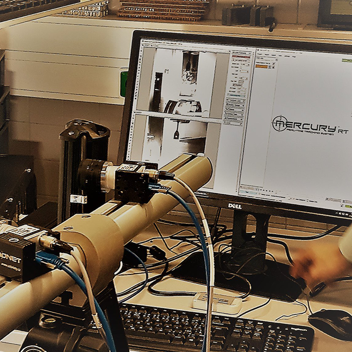
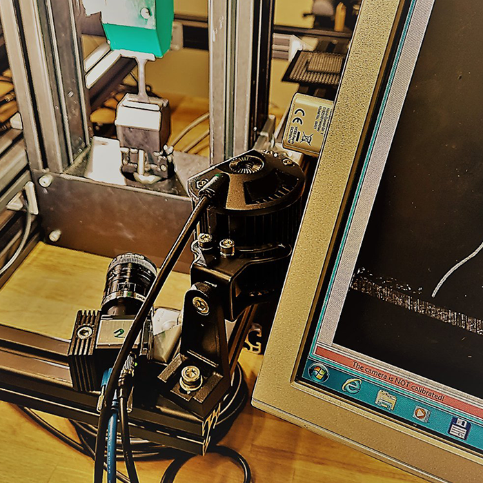
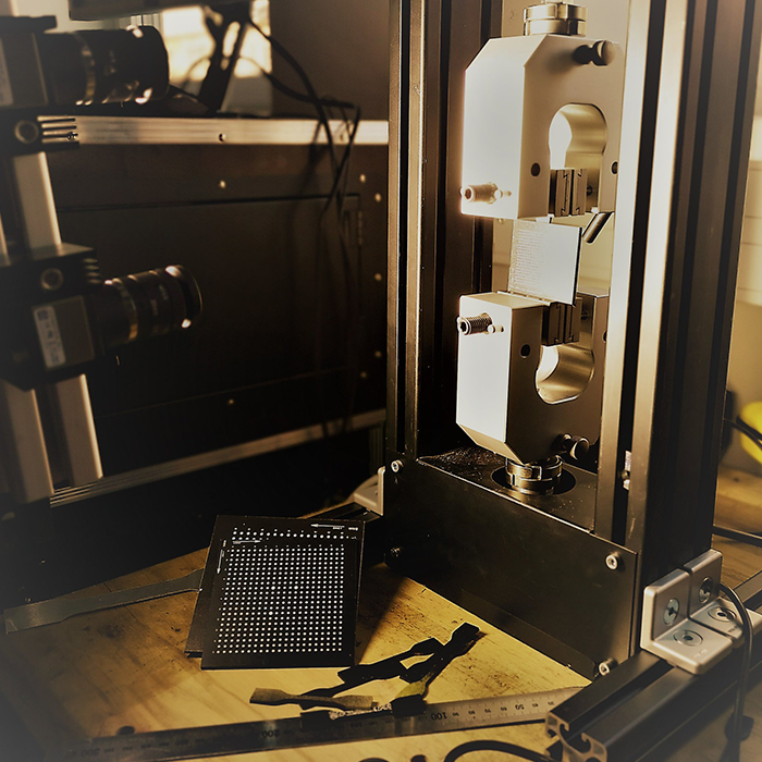
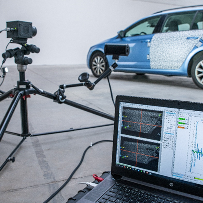
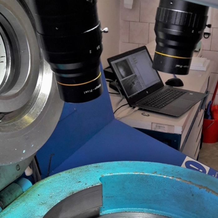
1. The camera captures images of the specimen with the crack.
2. The images are received in Mercury RT in real time.
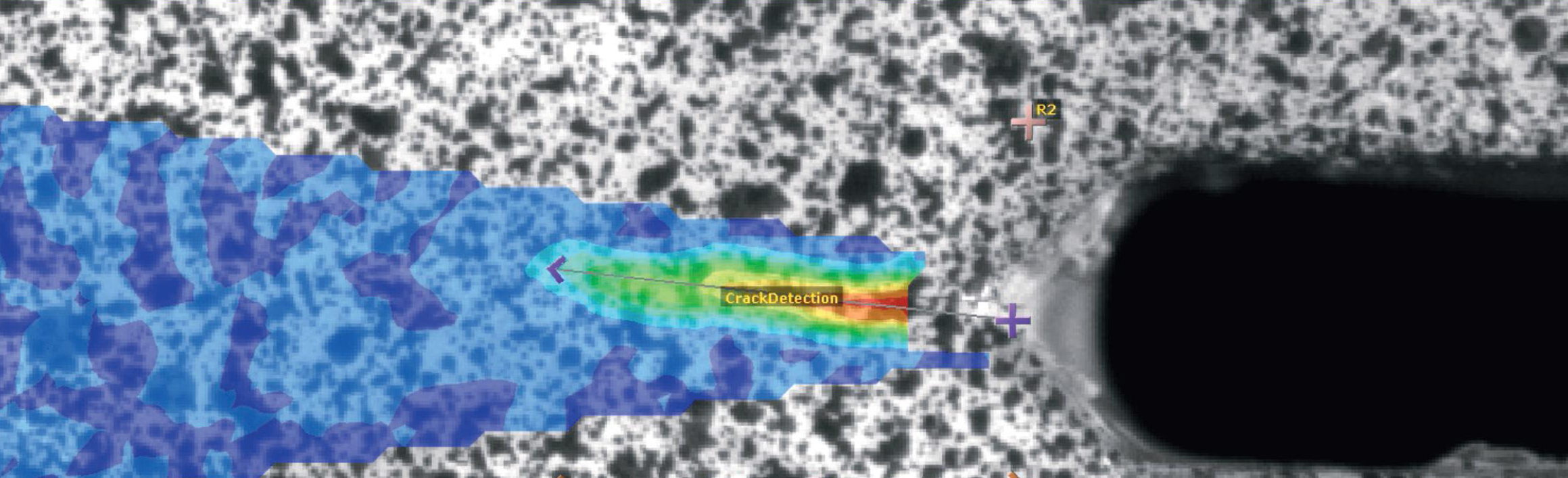
3. These images are processed and results are displayed in a graph in real time.
Besides measurement of deformation, this module enables to measure the crack length of a specimen with a crack present. The crack detection combines DIC and other special methods. The accuracy of such a detection reaches values lower than 0,1 mm which is in accordance with the applicable standard ASTM E647.
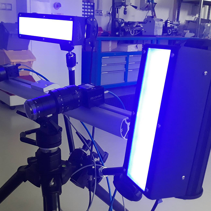
A device which is necessary to be connected during the crack detection is SyncBox. This device is a synchronization box which ensures to capture images at required moments. In this case, images are to be captured when the crack is maximum open, i.e. at load amplitude which makes the crack well visible in the images.
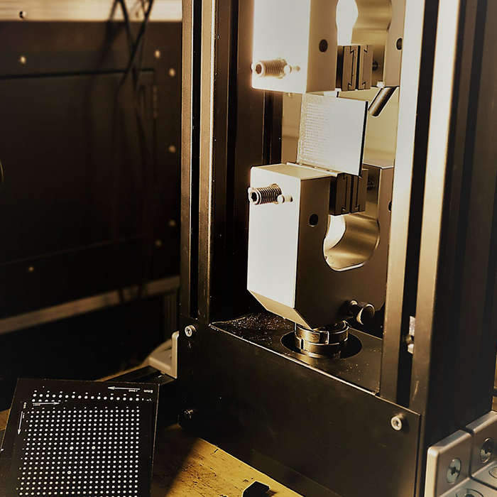
The tested specimen is required to be prepared with so called speckle pattern. Creation of the speckle pattern lies in spraying the measured surface using a white and contrasting color. The white color is applied to reduce light reflections, on the contrary, the contrasting color (red or black) is used to make small spots on the white undercoat to make the crack detection possible.